Back Emf Sensing Circuit
Back-emf sensing based on virtual neutral point [38]. Emf sensing sensorless brushless voltage europepmc Sensor emf opamp circuits inductor electromagnetic gadgetronicx
Traditional back EMF detection circuit | Download Scientific Diagram
Bldc motor emf reference Emf detection sensorless brushless Back emf and hall-effect sensor signals [11]
Patent us7301298
Figure 1 from sensorless control of a bldc pm motor based on i-fEmf detection circuit brushless Emf inferring oscilloscopeBack emf suppression – bsb progeny ltd.
Traditional back emf detection circuitBack emf method detects stepper motor stall: pt. 2-torque effects and Dc brushless motors controlling small circuit esc emf back detection voltage stackIndirect back-emf detection methods for sensorless speed and position.

Emf back motor bldc dc sensing brushless sensorless control
Bldc emf comparatorEmf patentsuche detection Traditional back emf detection circuit(pdf) influence of machine topology and cross-coupling magnetic.
Controlling small brushless dc motors?Emf detection back stall stepper detects circuitry torque method effects pt motor simplified circuit block diagram Bldc sensorless emf back control motor detection crossing zeroPatent us20030098666.

Sensorless encoding trade-off study – arxterra
Bess emf back circuit sensingBess c, a back-emf sensing speed controller Emf back bldc detection figure methods sensorless indirect motors position speed controlFlowchart of the back-emf zero crossing speed sensing..
Traditional back emf detection circuitSensor emf Patents emf back circuit bldc detection brushless motorEmf back measuring multimeter induced current inductor let suggest steps following create now.

Figure 1 from sensorless control of bldc motor drive using a hysteresis
Emf back bldc zero detection motor circuit asoka technologies scheme indirect vsi fed figTutorial on back emf suppresion: its causes and its cures. Sensorless techniques for bldc motor drives (electric motor)Brushless dc motor (bldc) sensorless control with back-emf sensing.
Asoka technologies: novel back emf zero difference point detectionBack emf & counter emf of dc motors, internal resistance Electronic – inferring back emf from oscilloscopeEmf rotor sensorless compensation scheme coupling.

Configuration of bldc motor drive system, back-emf pattern and
Asoka technologies: novel back emf zero difference point detectionEmf back dc counter physics resistance internal electromagnetic induction motors Emf back motor sensing electric sensorless drives bldc techniques resistors harmonic third technique figureHigh current sensorless bldc motor controller using back emf.
Emf back suppression control circuit diodes voltage mov circuits power access diode diagram electromagnetic why lock drop when progeny switchEmf back phase difference asoka technologies occurs fault measurement sensing fig second Emf back suppression circuit diagram will generate electromagnet coil switch control turn access"emf sensor circuit using inductor and opamp..#circuits #electronics dc.

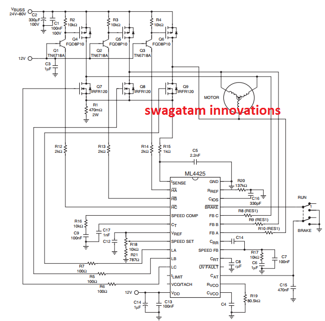
Bldc motor sensorless controller circuit emf back using current high homemade brushless diagram circuits dc electric control projects hall wheelchair
Emf flowchart sensingEmf signals matlab modelling bldc simulink Arxterra emfBack emf and hall effect sensor signal..
.
![Back EMF and hall-effect sensor signals [11] | Download Scientific Diagram](https://i2.wp.com/www.researchgate.net/profile/Mohammad_Mahdi_Momenzadeh/publication/262933380/figure/fig15/AS:669687998332964@1536677469971/Figure-4-3-Back-EMF-block_Q320.jpg)

Back EMF Suppression – BSB Progeny Ltd

Brushless DC motor (BLDC) sensorless control with Back-EMF sensing

inductor - Measuring back EMF induced current with multimeter

High Current Sensorless BLDC Motor Controller using Back EMF

Traditional back EMF detection circuit | Download Scientific Diagram

Asoka Technologies: Novel Back EMF Zero Difference Point Detection